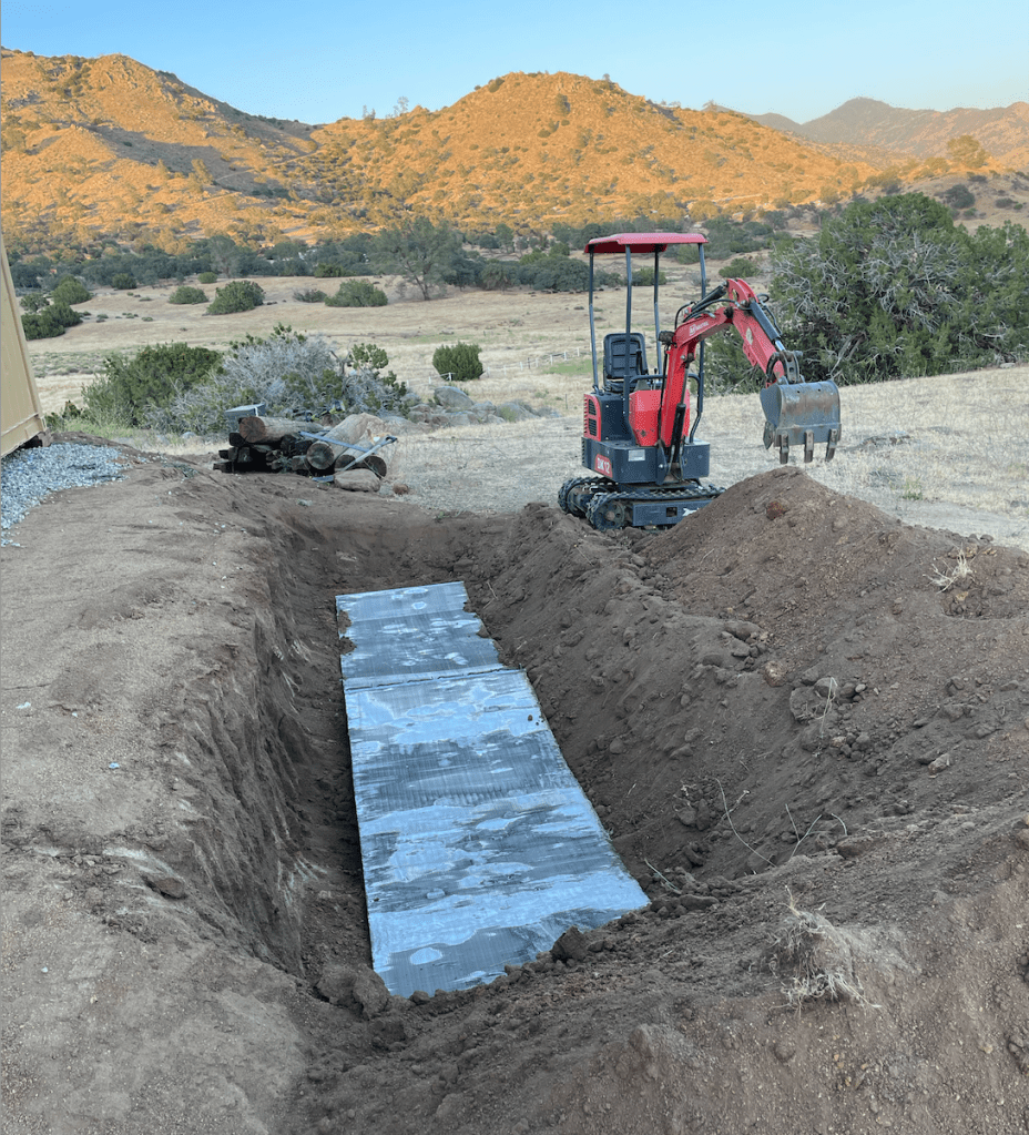
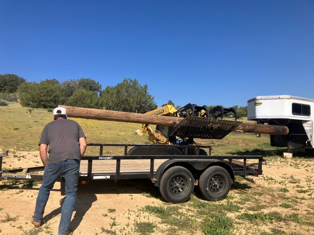
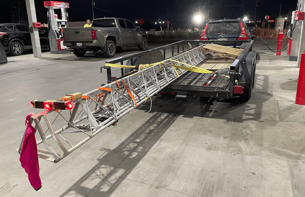
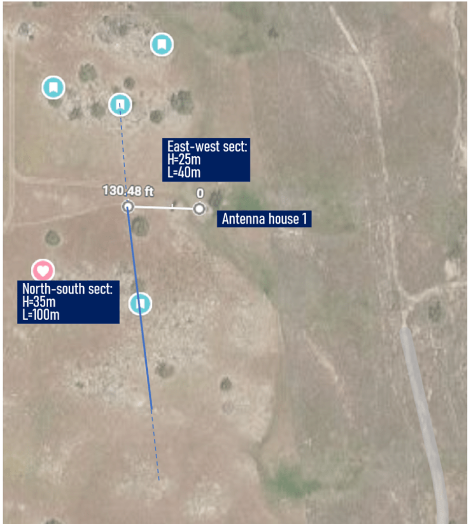
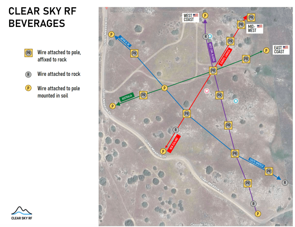
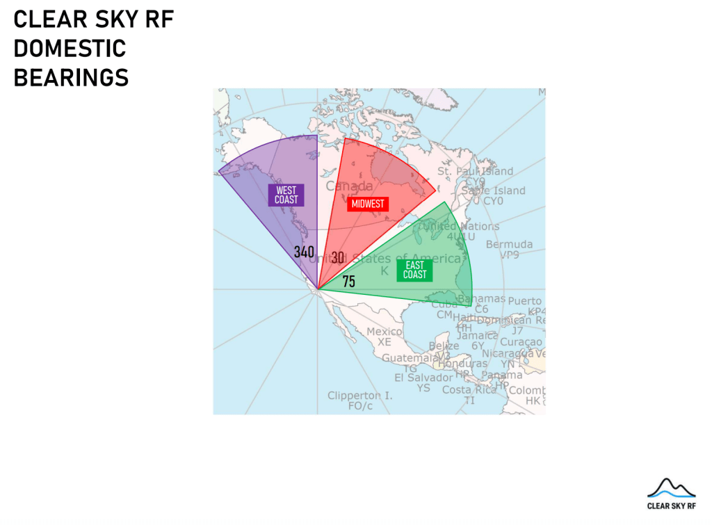
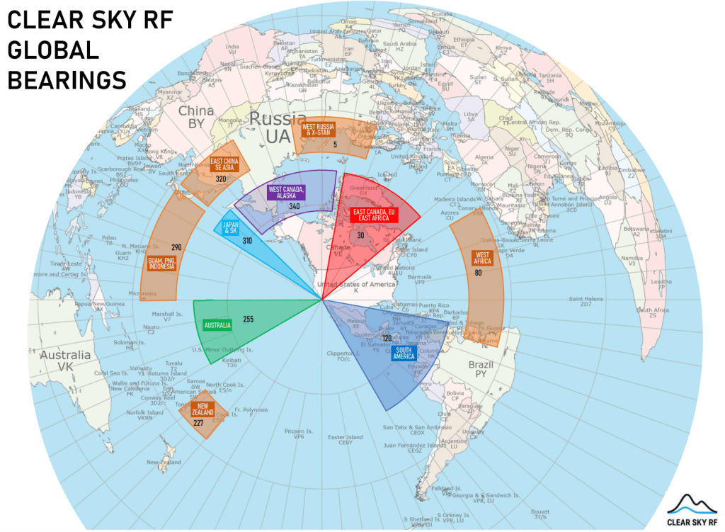
Our site features four Beverage antennas, each running 500+ feet, positioned at 45-degree intersections to cover the full compass rose. That’s a lot of wire, a lot of real estate, and a nontrivial cable run back to the lab from every corner of our 20-acre site.
The signal needs some help to survive that drop, so we’re building a dedicated amplifier from scratch using only in-stock parts, since receiving parts at a remote site like ours could take weeks. For example, we stockpiled Fair-Rite Mix 75 toroids from Digi-Key several months ago specifically because we knew this project was coming.
Why a custom amplifier?
Off-the-shelf preamps exist, but they’re optimized for narrower use cases. We need to cover the full span from VLF up through 160m and optionally 80m, from 25 kHz to 3.5 MHz.
That range creates a specific design tension: at the lower frequencies, the Beverage is electrically short relative to the wavelength, so it behaves more like a voltage source than a current source. At higher frequencies, it’s properly in Beverage mode — a traveling-wave antenna with a characteristic impedance around 400 ohms when terminated.
We landed on 2 kΩ as the input impedance, roughly 5x the terminated Beverage impedance, to achieve a reasonable compromise between the two regimes. Since the antenna is atmospheric noise-limited, we don’t sacrifice signal-to-noise ratio by going high-Z.
A few hours in LTSpice
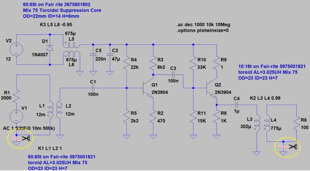
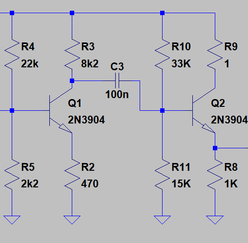
With those constraints locked in, we fired up LTSpice. A couple of hours later, we had a design: a two-stage BJT amplifier with an emitter follower (Q1) feeding a common-emitter gain stage (Q2), both biased at conservative operating points (1 mA and 3 mA collector current).
Transistor selection isn’t critical since noise performance here is dominated by the atmospheric environment, rather than the device — BC547, 2N3904, and 2N2222 will all work. We may compare them anyway out of curiosity.
A note on the simulation grounds
In one distinct way, the simulation doesn’t represent the physical build: the power supply, input signal, and output signal sections are intentionally not tied to a common ground. Connecting them would open the door to ground loop currents that would foul the signals we’re after. It would also defeat part of the purpose of the transformers (L1/L2, L3/L4, and L5/L6): the first two allow different ground domains to float relative to one another, denying undesirable ground currents a path.
That floating behavior makes LTSpice unhappy. Without a common reference, potential differences are limited only by stray capacitance and other parasitics — and we’re not even confident the model captures those accurately. The result is the simulator cheerfully reporting femtoamps and gigavolts, which contributes nothing to comprehension. Anyone who’s spent time in a physics simulator knows the phenomenon. So we tied them to a common potential for the sim, and the scissors symbols on the schematic mark where those connections get cut in the real build.
Power supply: keeping the junk out
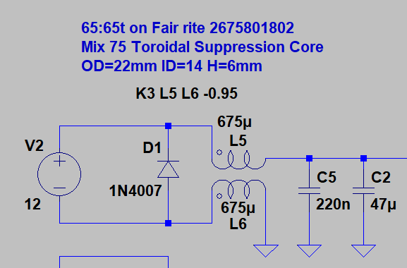
Power arrives via a second twisted pair on the same CAT-6 run at 26V, regulated down to 12V (not shown in the schematic). Right after the regulator is a common-mode choke that intercepts RFI and inverter line noise before it gets anywhere near the amplifier.
That choke is 65 turns wound bifilarly on a Fair-Rite 2675801802 Mix 75 suppression core. The datasheet doesn’t specify AL directly, but back-solving gives us approximately 3,000 nH/T², which works out to about 12.7 mH of inductance. At 25 kHz, that’s 2 kΩ of impedance. At 136 kHz, nearly 11 kΩ, and at 472 kHz, 38 kΩ. The choke pairs with a ceramic/electrolytic cap combination to form a low-pass filter that bounces common-mode noise back where it came from.
Input transformer: isolation with a DC path
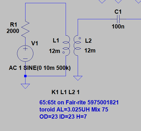
The input stage uses a 1:1 isolation transformer (un-un) rather than a direct connection to minimize static. The air at our site is extremely dry, and static buildup is an operational hazard. For instance, we’ve observed disconnected coax cables arcing over in the lab with nothing attached. The transformer provides isolation while still giving the antenna a DC path to ground.
We use the same core material, 65 turns bifilar again, this time on a Fair-Rite 5975001821 (AL = 3,025 nH/T²). Here’s the math to set the −3 dB point at 25 kHz:
L = 2000 / (2π × 25,000) = 12.7 mH
N = √(12,700,000 / 3025) ≈ 65 turns
The inter-turn capacitance isn’t a concern because even a generous estimate of 500 pF gives a reactance of 12.7 MΩ at 25 kHz.
The upper frequency limit is set by leakage inductance. For a well-wound bifilar toroid, leakage is typically 0.5–2% of magnetizing inductance:
L_magnetizing (65t) = 65² × 3,025 nH = 12.8 mH
L_leakage ≈ 1% = 128 µH
f_upper = 2000 / (2π × 128 µH) = 2.49 MHz
That puts us right at the 160m band target. The catch is that achieving 1% leakage requires tight bifilar winding. Sloppy technique would push leakage to 3–5%, dragging the f_upper down to 800 kHz–1.2 MHz and visibly costing us at the top of the band.
Amplifier stage
The two-transistor topology is straightforward. Q1 is an emitter follower with high input impedance and unity voltage gain. It drives Q2, a common-emitter stage with the actual power gain. Operating points are conservative and stable.
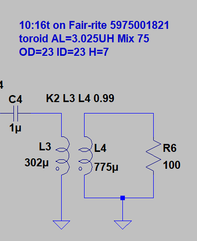
Output transformer: matching the cable
CAT-6 has a characteristic impedance of 100 Ω. The amplifier output impedance is about 40 Ω. The output transformer bridges that gap.
We use the same Fair-Rite 5975001821 core, AL = 3,025 nH/T². The impedance ratio is 2.5:1 (100 Ω to 40 Ω), which gives a turns ratio of √2.5 ≈ 1.58. In practice:
N_primary = 10 turns → L = 100 × 3,025 nH = 302 µH
N_secondary ≈ 16 turns
Then, we check the frequency response:
- At 136 kHz: XL = 258 Ω — about 6.4× source impedance, ~1 dB rolloff ✓
- At 25 kHz: XL = 47.5 Ω — ~1.2× source impedance, ~7 dB rolloff ✓ (within budget)
- At 2 MHz: XL = 3.8 kΩ — well above source impedance, flat ✓
The 7 dB rolloff at 25 kHz looks steep on paper, but signals at the very low end are strong. We’re comfortable with it.
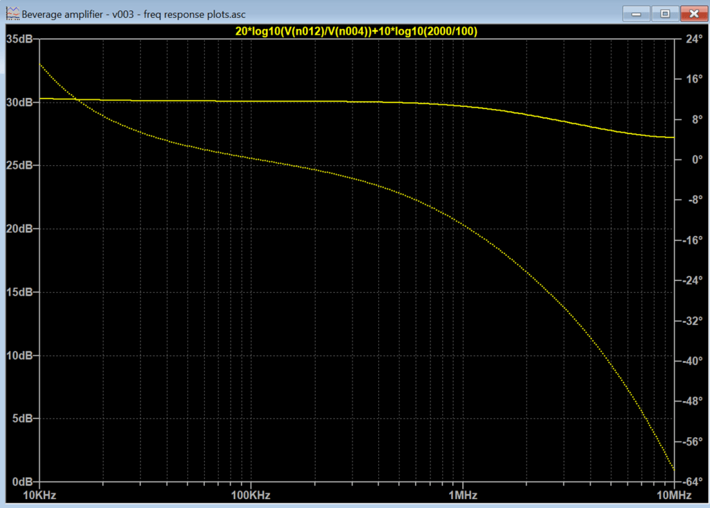
Simulated performance
The assembled simulation shows approximately 30 dB power gain, flat from VLF to 1 MHz, dropping to 29 dB at 1.8 MHz and 28 dB at 3.5 MHz.
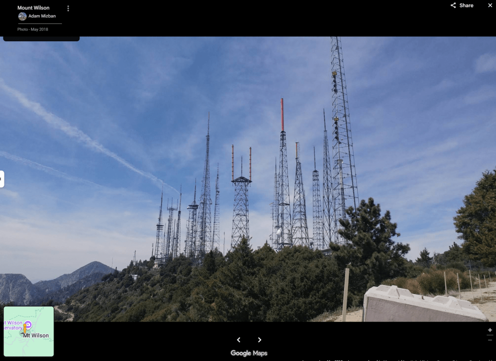
The Mt. Wilson stress test
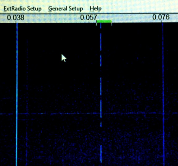
The AM broadcast cluster on Mt. Wilson near Los Angeles, roughly 80 miles south, is the obvious stress case. Two stations, 600 kHz and 810 kHz, were injected at a pessimistic 1 mV each (a conservative assumption). It looks messy in the time domain.
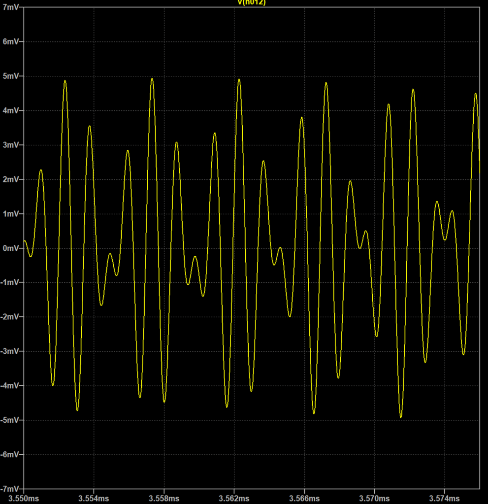
Intermodulation products are 70 dBc down in the frequency domain. We’ll take it.

Next step: build the thing
The simulation is solid, and the parts are on hand. Time to wind some toroids. We’ll report back.