Our container lab sits on decomposed granite, and the ground is absolutely terrible for driving ground rods. When we needed a serious RF ground for our 630m band work, the conventional answer — an 8-foot copper-clad rod hammered vertically into the earth — wasn’t going to happen. The rock laughs at you.
So we stripped a dead air conditioner instead.
Taking inspiration from the NEC
Our existing safety ground works fine at 60Hz. However, at LF/MF frequencies, its inductance makes it useless as an RF reference. We need a separate, dedicated low-inductance, low-impedance path to earth for the RF system.
Which brings us to a useful detail in the National Electric Code Section 250.53(G). It’s intended for safety grounding, but the physics doesn’t care. It states that if bedrock or other impediments prevent driving a standard 8-foot rod vertically (or at up to 45 degrees), it’s permissible to bury it horizontally at a minimum depth of 30 inches.
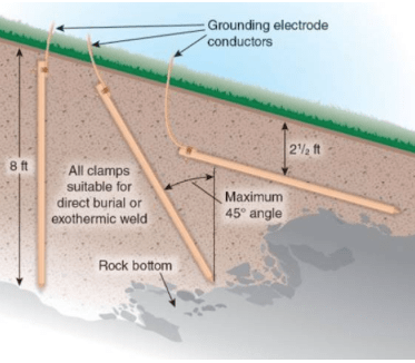
Image source: National Fire Protection Association
This gives us an out for our predicament. How? You see possibilities once you understand why horizontal burial works just as well as vertical. Let’s dig in.
Orientation barely matters, while surface area is everything
The key insight lies in the geometry of how resistance works in soil. If you model the earth around a buried electrode as concentric hemispherical shells, the innermost shells, i.e., the soil immediately surrounding the electrode, dominate the total resistance. Beyond a few multiples of the electrode’s largest dimension, additional soil contributes almost nothing.
The resistance of each shell of thickness (dr) at radius (r):
dR = (ρ · dr) / (2πr²)
Integrating from the electrode surface radius (a) to infinity:
R = ρ / (2πa)
Here’s the practical implication: what matters is the effective radius a, which is determined by the electrode’s surface area in contact with the soil, not whether it’s pointing up or sideways. A horizontal rod at 30 inches deep achieves soil contact of the same quality as a vertical one. Current just spreads outward horizontally instead of downward.
This is good news for anyone with bedrock close to the surface, and great news if you happen to have access to something with a lot more surface area than a rod.
Enter the dead air conditioner
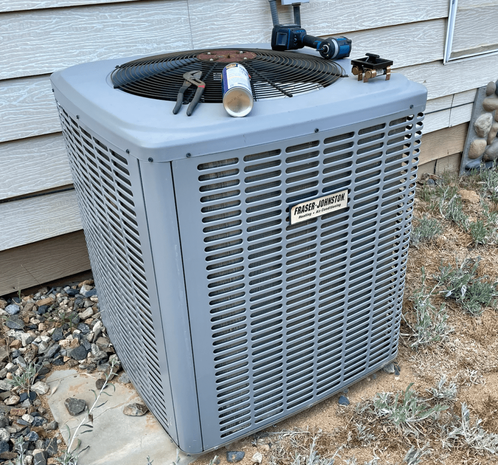
When a neighbor was upgrading her HVAC system, we offered to haul away the old Fraser-Johnston condenser unit. We saved her the disposal headache and got a potentially useful hunk of metal.
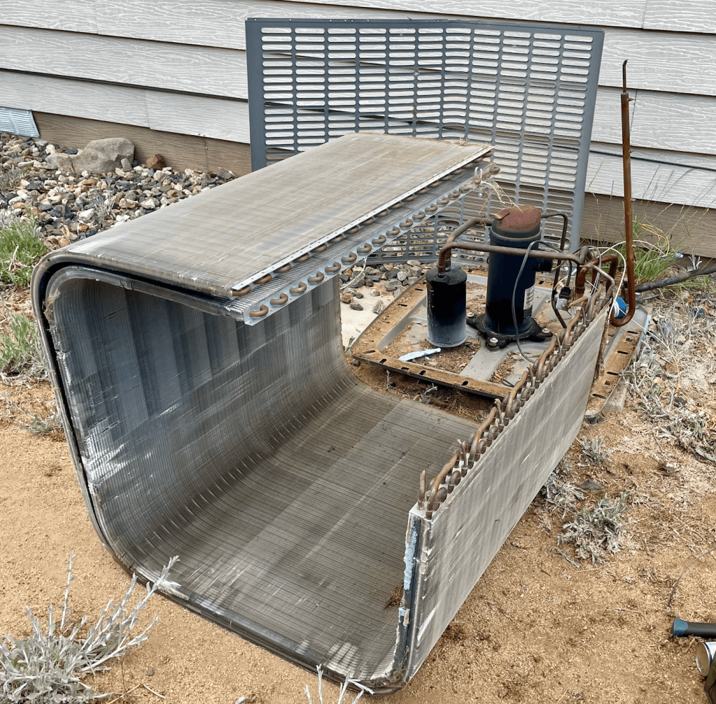
Once we stripped it down, we found RF gold: a massive condenser coil. It’s a large, U-shaped assembly of copper tubing bonded to aluminum fins. Unrolled flat, it measures roughly 1.5 × 5 meters, providing about 7.5 square meters of copper-bonded surface area.
Compare that to a standard 8-foot × 5/8-inch ground rod, which has an effective surface area of about 0.04 m². Let’s run the numbers for decomposed granite soil (resistivity ρ ≈ 10,000 Ω·m, a reasonable estimate for dry granite):
| Electrode | Effective radius | Resistance to remote earth |
| Standard 8 ft rod | ~0.008 m | ~200,000 Ω |
| Copper/aluminum plate, 1.5 × 5 m | ~1.55 m | ~1,000 Ω |
That’s roughly a 200:1 improvement over a standard rod in our specific soil conditions.
A note on the oxidized copper: the coil has surface oxidation, as you’d expect from years of outdoor service. Copper oxide remains sufficiently conductive at these frequencies, so it doesn’t meaningfully affect performance.
One more wrinkle: skin depth in soil
Soil has a skin depth just like a conductor, and the depth at which RF current density falls to 1/e of its surface value:
δ = √(ρ / (πfμ₀))
Where ρ is soil resistivity, f is frequency, and μ₀ = 4π × 10⁻⁷ H/m.
For our decomposed granite at 472 kHz, that works out to roughly 15 meters.
The practical implication is that at our primary operating frequency, the current penetrates deeply enough that the burial depth of our electrode matters much less than its lateral extent. We’re well within the quasi-static near-field regime: the plate’s 5-meter dimension is about λ/300 at 472 kHz, which means we don’t have to worry about resonance or standing-wave effects.
Into the ground
We dug a trench (as deep as humanly possible without involving dynamites) next to the container lab using a mini excavator, laid the coil flat, and buried it at approximately 2 feet below grade. We may add more backfill on top, which would only improve performance because more soil mass above the plate means better coupling to the surrounding earth.
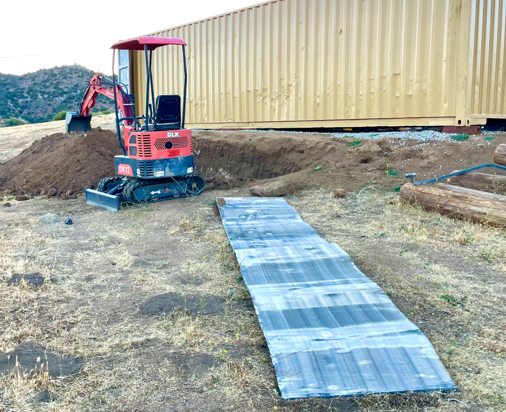
As a natural Faraday cage, the container lab is the most suitable location for this ground reference. Bonding the plate to the RF entry point at the lab keeps the connection path short and low-inductance, which is exactly what we need.
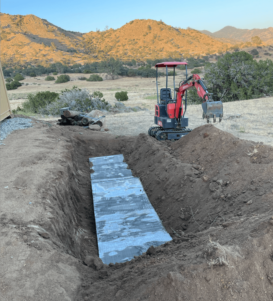
The key to low inductance is to keep the connection length between the grounding plate and the container lab as short as possible. We have about 4’ to cover, which is far closer than most people can achieve. We also use two AWG6 conductors (code only requires one) to further reduce inductance.
Results, not paperwork
A purpose-built ground system for a research site like ours with engineered plates, burial contractors, and the works would require a budget line, a procurement process, and probably at least a few months of waiting. We did this on a Tuesday with our mini excavator and a condenser coil headed for the scrap pile.
The physics says it should outperform a standard rod in our soil by roughly two orders of magnitude. We’ll validate that against measured ground resistance once the bond is complete. But the modeling is solid, the plate is in the ground, and the price was right.
We build minimum viable infrastructure grounded in actual physics to test theories and validate ideas — enabling researchers to deploy experiments before anyone’s written a scope of work or grant proposal.
Ready to run your own budget-friendly RF experiment? Drop us a line.

