Tag: ham-radio

  • Beverage Antennas for Low-Band, Weak-Signal Research

    To set the stage for future data collection and research opportunities, one of our inaugural projects was a series of Beverage antennas for long-wave, low-frequency bands (receive only). 

    Why Beverage antennas?

    They’re easy and quick to execute. Since they don’t need to be high off the ground, we can mount them on a few 4x4s or telephone poles to gather meaningful data with an MVP setup, instead of spending months on infrastructure.

    This post explores how we meet the various criteria for building a Beverage antenna and the specifics of our setup for long-wave, low-frequency bands.

    Criteria for building a receive antenna for low-band, weak-signal research

    Beverage antennas can receive signals from one or both ends. Weak signal research requires the ability to “aim” where the antennas receive the signal from. Additionally, we need the ability to attenuate/reject undesirable signals to increase the signal-to-noise ratio and, therefore, the ability to decode signals.

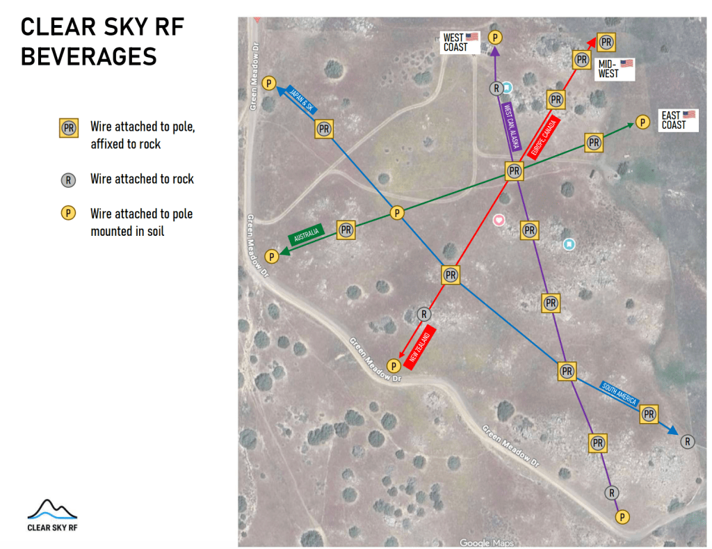
    A successful Beverage antenna setup for low-band weak signal research goes beyond theories and calculations. Simply finding a site that can accommodate the length of the antenna is quite a challenge. Here are the top considerations and how our 20-acre property enables us to set up four antennas aiming at nine general regions across the globe.

    ClearSkyRF Beverage antenna planning

    • Technical requirements. Beam pattern design is a tradeoff between desirable technical characteristics (gain, directivity, lobe beam width). The wider the beam, the more you receive, but you also collect more undesirable signals (i.e., noise). While a narrower beam provides more focus, you’d need more antennas to cover all orientations.
    • Lobe overlaps. You need a sizable property to achieve the ability to select where the signals come from and orient the antennas so that the lobes overlap just enough to minimize gaps. 
    • Financial costs. Cables are costly, while low-frequency means a long wavelength. A Beverage antenna must be at least half a wavelength long. The setup shown above requires 3,000’+ of connecting cables.
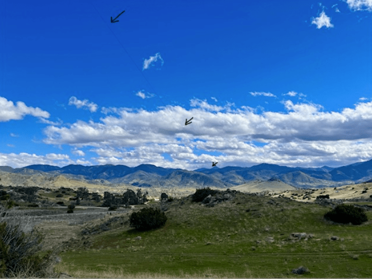
    • Physical support for cables. Long cables sag. Our property offers several opportunities where the long antennas intersect at a 45-degree angle, allowing us to set up physical support at a practical cost.
    • Real estate. Studying long-wavelength signals means you need acreage to accommodate long antennas. The blue line in the above diagram is 1,500’ long, stretching across the entire property. The site has a fairly “square” shape, allowing us to set up long-wavelength antennas in multiple directions.
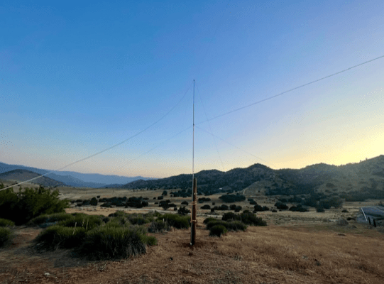
    • Terrain and mounting opportunities. The property must provide opportunities for mounting antennas so the intersection angles work with the antenna field design. In most cases, researchers must invest time and resources in foundations for anchoring antenna poles or towers. Our property, on the other hand, features rock formations perfect for anchoring antenna poles quickly and cost-effectively.
    • Soil characteristics. Beverage antennas work best on rocky/sandy/electrically lossy soil, and our property has just the right type of soil for such research.

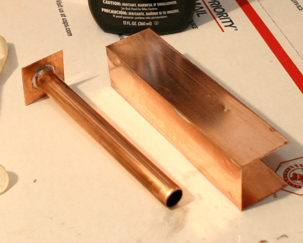
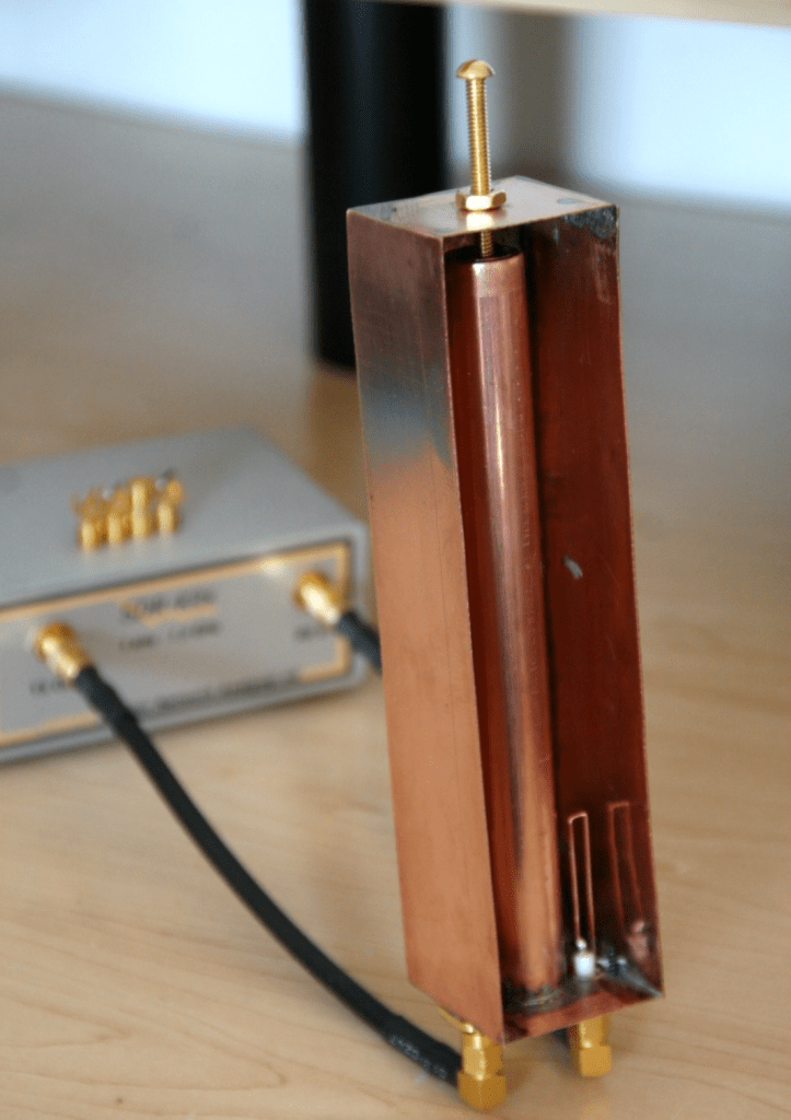
    The practical implementation of our Beverage antenna series

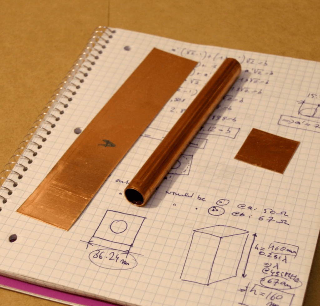
    First, we identify the wavelength to focus our study on.

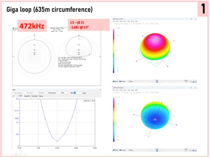
    472 kHz is the sweet spot. The physical dimension still allows for practical implementation on the property. Meanwhile, there are enough people studying it so that we’re not doing this work in a vacuum.

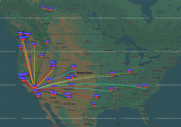
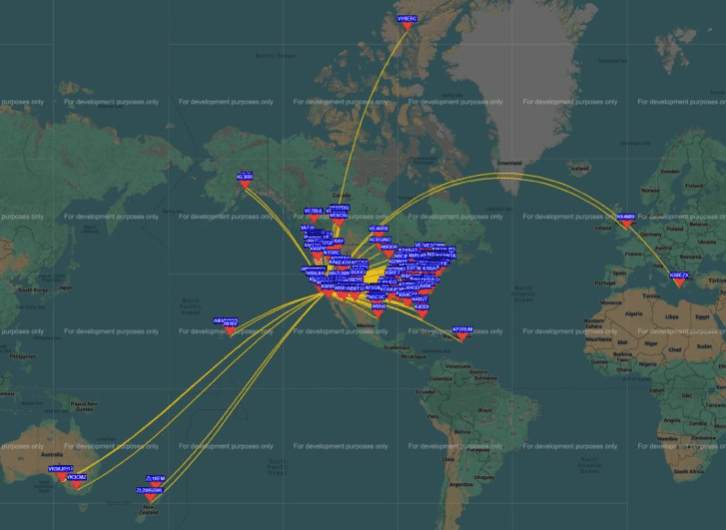
    Then, we determine where we pull signals from by segmenting the world and focusing on areas worth isolating, i.e., people are transmitting signals. We started with domestic bearings, segmenting the U.S. into three regions: the West Coast, the Midwest, and the East Coast.

    ClearSkyRF domestic bearings

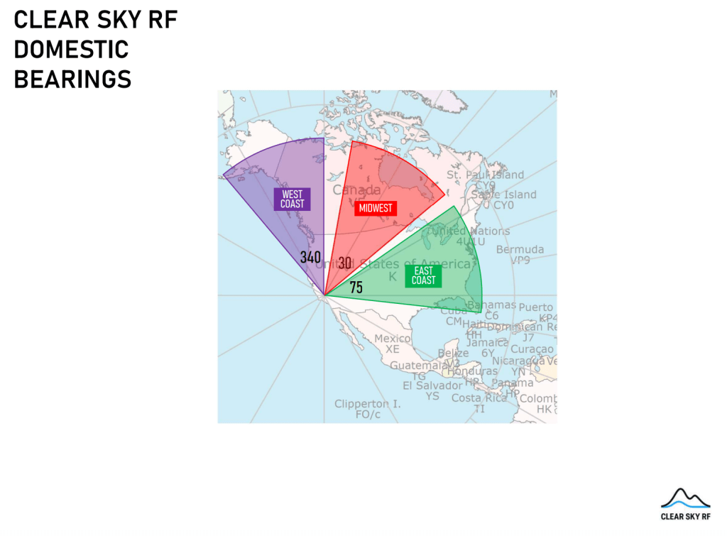
    Next, we consider interference sources to inform the antenna’s directionality. Los Angeles is about 100-150 miles south of our site. If we set up an N-S antenna, we’d catch a lot of noise from the city. Instead, we leave a gap between the 340-degree and 30-degree antennas to minimize undesirable signals.

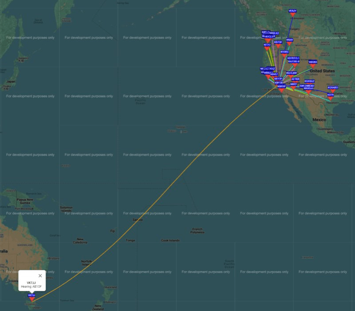
    For weak signal research, we want to focus on international targets because domestic ones (while we still want reasonable coverage) are “too easy.” So, we identify regions we can reach on an international map:

    ClearSkyRF global bearings

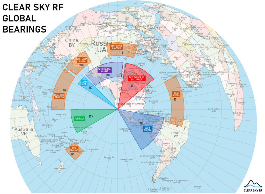
    Besides places we can reasonably reach (proven in a few preliminary test runs), we map out “boundary challenges” — stretch targets that don’t have many practical examples of communications on the two lowest bands covering such vast distances.

    So, why does this approach make sense?

    This setup uses fairly traditional and common communication methods and systems to hone weak signal operations. Once we refine the details and achieve a world-class sensitivity level, we have the groundwork for future research. For example, we can use the data and insights for different applications, such as geological phenomena recording, soil studies, and more.

    If you have a research project that can use this Beverage antenna setup, we’d love to hear from you! Get in touch to explore collaboration opportunities. 

  • Antennas in Various Stages of Operation on Our Site

    As of January 2026, we have several antenna setups that are in various stages of operation or repair on our site. Here’s an overview.

    The start of the Giga Loop

    A full-wave 630m loop at varying heights ranging from 10 to 100ft off the ground. In practice, the feedpoint impedance is way off from the simulations, but that’s okay. As of Spring 2025, it is partially dismantled for construction work on the property, but even with half the wire coiled up, it still picks up stations from across the world.

    It starts off here and circles a part of the property:

    Perhaps because of the capacitive loading and its proximity to ground, it resonates much lower than  I anticipated/simulated, and the feedpoint impedance is miles off from where it should be.

    We use the learnings from this experiment to build our Giga Loop, which will cover over 15 acres.

    A fan diapole

    This antenna hung about 75 feet over a canyon on our property. The feedline was balanced at the 600-ohm line. This antenna is currently down, mostly because the feedline was not practical due to the distance to the shack — it constantly got tangled up. I will need to either build a remote tuner or maybe find a source of 450-ohm ladder line at a reasonable price, as I might need about a quarter mile.

    I love the simplicity of a fan dipole, also strung over the canyon. This is fed by a current balun and RG-6 Cable TV coax at 75 ohms, because it is cheap for long runs and has no significant loss at HF for resonant antenna use.

    Vertical Antennas

    I’m not exactly a “vertical enthusiast” (they’re noisy), but this contraption is quite useful for transmitting. It has four radiating elements and eight elevated radials. Fed with one 75-ohms coax for all 6 bands.

    Another dual bander: vertical for 80, inverted L for 160. All wire. Strung over a canyon with six radials going east-west and the “L” going north-south. The radiation pattern is almost omnidirectional.

    Sometimes, temporary antennas stay up a little longer than planned. Almost a year ago, I planted a few 2x4s into the ground as a makeshift “mast” to get something in the air for 6m, 2m, 20m, and 40m. All are fed with RG-6, as I had a couple of 500ft spools lying around.

    The 2-meter antenna is a monopole with radials bent to match the 75-ohm impedance of the cable. The physical insulator is a spark plug. The 6-meter antenna on the right is a vertical dipole. No balun was used, even though it is a balanced antenna. It was supposed to be up for a day, and I was out of balun materials. 

    These two inverted Vs share a 4×2 “mast” (pole? stick? contraption? eyesore!) Both coaxials are RG-6. Balun is 1:1. 

  • A Back-to-Basics WSPR Beacon Setup (It Reached Tasmania!)


    For me, Amateur Radio is about designing and building equipment, experimenting, and learning. I have done so for/on almost every amateur frequency, from 630m to X-band. Rag chews or contesting do not speak to me much. My antennas are mostly omnidirectional, simple, and resonant, including a full-wavelength loop on 472 kHz. However, reality forces me to settle for a 630m loop that is just a fraction of a wavelength above ground.

    I’ve been working on this back-to-basics WSPR beacon since June, 2025.

    If you pick up my WSPR beacon on 80m, this is what the signal came from: a homebrew built-from-first-principles design. The oscillator is a 74HC00 NAND gate. The NTSC color burst crystal was modified with a Sharpie to oscillate on 3570.1 kHz. 

    A second NAND gate is used to gate the oscillator signal, producing CW. I sign off my WSPR transmissions with my callsign in CW.

    The microcontroller is an ATTiny88 in some Arduino form factor. I never developed an interest in object-oriented programming, so I usually wipe the bootloader and write my own code in assembler or sometimes a higher-level language.

    Time comes from a DS3121 RTC. Drift is deep sub-second per day, but it needs occasional tuning to keep the drift under a second.

    WSPR modulation is created by driving a low-pass-filtered PWM signal into a reverse-biased red LED, which is used as a varactor in the crystal circuit. A few pF is enough to pull the crystal over the ~4.5Hz range dictated by the WSPR protocol.

    The PA is a 74AC240 with two times 4 drivers driven differentially. I measured the differential output impedance to be about 17 ohms, so I use a 5:1 balanced-to-balanced impedance transformer (a balbal?), giving about 90 ohms to the antenna port. LPF is a 5th-order differential Butterworth LC filter. I know I should not have used an SMA connector, but I was originally not planning on a differential drive.

    Power is a single Li-Ion cell, with no power conversion. This causes about 20Hz of drift over the supply range. The 2Ah cell powers the beacon through the night. 

    The transmission line to the antenna is about 30m / 100ft of Cat-5 network cable.

    The antenna is an inverted V with the apex at 30ft / 10m, but unfortunately, 100mW will not boil off any clouds. 

    One night of operation on one battery charge yields the following. I’m rather pleased with that for 100mW of power into an inverted V at one-eighth of a wavelength high.

    It was even spotted in Tasmania — with 100 mW, on 80m! On a couple of occasions, it got to Alaska, which I thought was pretty good, but Exceter in Tasmania is 12,839km. Almost 130,000 km per watt, with an NVIS antenna made from garbage wire (24 Ga CCA, so aluminum).

    If you pick up my WSPR beacon on 20m, the story is somewhat different. This is a more “traditional” approach, using an Si5351A CMOS clock generator programmed around the 20m WSPR frequencies on both sides of 14.097100 MHz.

    The rest is mostly the same; the LVDS 3.3V p-p signal is boosted to 5V with a 74HC gate, and the PA is a 74AC240, here driven at 6V.

    When loaded between 15 and 20 ohms differentially, Pout is around 300mW, and PA dissipation is about a Watt before the output filter. The transmission line (CAT-5) is over 20 ohms resistively alone. The ERP is about 100mW into a resonant inverted V about 7 meters up. 20m is an easy band, so down under and “up over” at VY0ERC showed up within hours.

  • Creative Antenna Experiments Series: A Cavity Filter for 70cm Wavelength

    Our mission at ClearSkyRF is to provide a low-threshold experimental environment that unleashes new forms of creativity and scientific insight.

    Using what’s at hand and making the most of your surroundings is critical to gaining quick insights without the high price tag associated with formal experimentation.

    In this series, I share documentation from my past experiments — hopefully to spark ideas and conversations.

    First up, here’s a cavity filter for 70cm wavelength: